About CF / D-MT Compressed Air Filters
Pressure differential gauge
All CF filters are fitted with a differential pressure gauge as standard which indicates the effective pressure drop across the filter and its filter element.
High filtration quality
Our pleated media filter elements guarantee excellent filtration quality and a long service life thanks to a larger filtration surface.
Robust body and structure
Our filtration bodies are made of aluminum and bronze, an alloy which offers better resistance over time. These are covered with a baked epoxy paint of RAL 5012.
COMPRESSED AIR FILTER CF / D-MT / WS Series
CF Series
From 60 to 3000 m3/h Max. pressure 16 bar
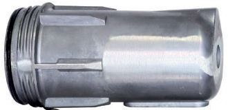
Optima offers 5 different grades of filtration elements, each easily identifiable by their finish (P,M,S,X,A) : different colored EndCap and a plastic-coated label on the filter simplifies maintenance operations it’s legibility over time. The cylindrical inner and outer cages are made from perforated sheet metal. The cartridge screws directly onto the threaded rod of the filter, thus providing improved sealing. This operation is simplified by the centering cone located at the bottom of the cartridge. The caps are made from industrial grade plastic ,guaranteeing high resistance to chemicals, heat and mechanical stresses, the seal is ensured by a nitrile 0-ring.

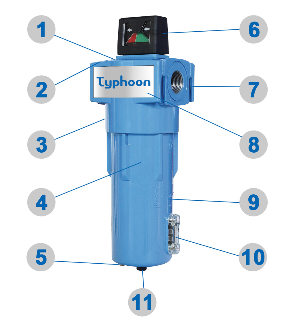
1. Model Identification
Area of identification plate for each filter
2. White Arrows
Removable white arrows to show the direction of air flow
3. Depressurization Hole
4. Body
Epoxy / RAL 5012
5. Manual Drain
6. Pressure Gauges
Different gauges for models: CF006 - CF012 & CF020 to CF300
7. Connections
2 parallel connection points
8. Surface Plate
White face plate available for customization
9. Tighten and Loosen Marks
10. Sight Glass / Condensate Level
11. Automatic Drain
 Housing in aluminium and bronze for a better durability.
The grade P filtration element is comprised from cellulose acetate fibers in the form of pleated paper.
The grade M,S and X filtration elements are equipped with a media offering 4-phase filtration with an outer and inner pleated layer made from polypropylene and 2 superposed pleated layers in the middle made from borosilicate microfibers.
The grade A filtration element is equipped, in addition to grades S and M, with a media composed of activated carbon (32%) to absorb oil particles.
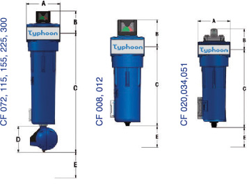
Technical Specifications: CF Series
|
|
Flow Rate
|
|
Dimensions
|
Max. Working Pressure
|
Weight (kg)
|
Element Ref. #
|
|
MODEL #
|
m3/min
|
m3/h
|
CFM
|
Connection
|
A
|
B
|
C
|
D
|
E
|
bar
|
PSI
|
|
CF-006
|
1
|
60
|
35
|
1/2”
|
89
|
57
|
181
|
-
|
80
|
16
|
232
|
1
|
CY 08051
|
|
CF-008
|
1.3
|
80
|
46
|
1/2”
|
89
|
57
|
215
|
-
|
114
|
16
|
232
|
1.1
|
CY 11541
|
|
CF-012
|
2
|
120
|
71
|
3/4”
|
89
|
57
|
215
|
-
|
114
|
16
|
232
|
1.08
|
CY 11541-1
|
|
CF-020
|
3.3
|
200
|
117
|
1”
|
120
|
96
|
282
|
-
|
155
|
16
|
232
|
2.7
|
CY 17475
|
|
CF-034
|
5.6
|
340
|
198
|
1-1/2”
|
120
|
96
|
282
|
-
|
155
|
16
|
232
|
2.82
|
CY 17475-1
|
|
CF-051
|
8.5
|
510
|
300
|
1-1/2”
|
120
|
96
|
382
|
-
|
255
|
16
|
232
|
3.36
|
CY 27475
|
|
CF-072
|
12
|
800
|
424
|
1-1/2”
|
162
|
107
|
571
|
125
|
333
|
16
|
232
|
6.15
|
CY 34694
|
|
CF-115
|
19
|
1,000
|
671
|
2”
|
162
|
107
|
882
|
125
|
662
|
16
|
232
|
8.58
|
CY 67594
|
|
CF-155
|
25.8
|
1,500
|
911
|
2-1/2”
|
200
|
131
|
671
|
125
|
383
|
16
|
232
|
13.9
|
CY 41125
|
|
CF-225
|
37.2
|
2,200
|
1,314
|
3”
|
200
|
131
|
928
|
125
|
660
|
16
|
232
|
16.45
|
CY 69125
|
|
CF-300
|
50
|
3,000
|
1,766
|
4”
|
200
|
131
|
928
|
125
|
660
|
16
|
232
|
15.45
|
CY 69125-1
|
Maximum temperature: +80 °C (±100 °C or higher temperatures. Please contact us) ** Minimum re:+ 1 °C

|
MODEL #
|
P
|
M
|
S
|
X
|
A
|
|
|
Class
|
3
|
2
|
1
|
-
|
-
|
|
|
|
Air Quality
|
Filtration Impurities (Mocron)
|
3
|
1
|
0.01
|
0.02
|
114
|
|
Complies with
|
Efficiency (mg/m3)
|
5
|
1
|
0.1
|
-
|
-
|
|
ISO standard 8573-1
|
Residual Oil Content (mg/m3)
|
1
|
0.1
|
0.01
|
0.002
|
0.003
|
|
Filter Type
|
Coalescing
|
Oil Vapour
|
|
Particle Removal Water & Oil Aerolsols
|
3um
|
1um
|
0.01um
|
0.01um
|
0.01um
|
|
Cartidge Presure Drop (bar)
|
0.02
|
0.03
|
0.09
|
0.1
|
0.11
|
|
Cartidge Presure Drop (PSI)
|
0.3
|
0.45
|
1.3
|
1.4
|
1.6
|
** The above conditions are based on an absolute pressure of 1 bar (14 PSI) a temperature of +20 °C and a relative vapour pressure of 0.6 the initial pressure drop values are given for the nominal flow rate for a single dry cartridge.
|
Flow Rate Correction Factors as a Function of Service Pressure
|
|
bar
|
1
|
2
|
3
|
4
|
5
|
6
|
7
|
8
|
9
|
10
|
11
|
12
|
13
|
14
|
15
|
16
|
|
PSI
|
14
|
29
|
43
|
58
|
72
|
86
|
100
|
115
|
130
|
145
|
160
|
174
|
189
|
203
|
217
|
232
|
|
Correction Factor
|
0.25
|
0.38
|
0.5
|
0.65
|
0.75
|
0.88
|
1
|
1.13
|
1.25
|
1.38
|
1.5
|
1.63
|
1.75
|
1.88
|
2
|
2.13
|
To optimise condensate elimination ,TyphoonCompressor filters can easily be fitted with our electronic drain traps. TyphoonCompressor a compressed air treatment specialists also manufacture a complete range of refrigeration and absorption dryers and accessories (oil/water separators, etc.)
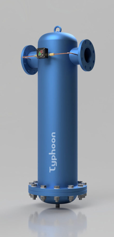
Technical Specifications: D-MT Series

|
MODEL #
|
D3001MT
|
D6002MT
|
D9003MT
|
D12004MT
|
D15005MT
|
D18006MT
|
|
Flow Rate (m3/h)
|
3,000
|
6,000
|
9,000
|
12,000
|
15,000
|
18,000
|
|
Flow Rate (CFM)
|
1,750
|
3,500
|
5,250
|
7,000
|
8,750
|
10,500
|
|
Connection
|
4” FL
|
6” FL
|
6” FL
|
8” FL
|
8” FL
|
10” FL
|
|
|
A
|
450
|
600
|
650
|
700
|
750
|
800
|
|
|
B
|
1.052
|
1,264
|
1,366
|
1,418
|
1,480
|
1,580
|
|
Dimensions (mm)
|
C
|
90
|
150
|
150
|
150
|
150
|
200
|
|
|
D
|
150
|
150
|
150
|
150
|
150
|
150
|
|
Max. Working Pressure (bar)
|
16
|
16
|
16
|
16
|
16
|
16
|
|
Max. Working Pressure (PSI)
|
232
|
232
|
232
|
232
|
232
|
232
|
|
Max. Inlet Temp
|
80
|
80
|
80
|
80
|
80
|
80
|
|
Weight (kg)
|
81
|
156
|
240
|
310
|
398
|
400
|
|
Element Reference
|
CY 69125-1 P/M/S/A/X
|
|
Element QTY
|
1
|
2
|
3
|
4
|
5
|
6
|
Technical Specifications: WS Series | Cyclone Water Seperators
Water separator is one of purification products without elements which is used in front of the coalescing filters to protect against bulk liquid contamination ,where excessive cooling takes place in air receivers and distribution piping.
Existing problems:
Compressed air system have bulk liquid which bring pipeline corrosion, the damages of valves ,air cylinder and tools, reduce the efficiency of after air cooler and heat exchanger.
Futures:
High speed cyclone
Aluminum alloy die-casting housings.
Anti-corrosion treatment. No secondary pollution.
Static rotary vane. Keep 99.9% high efficiency separation.
70 m³/min flow rate.
Low pressure loss. Differential pressure is 0.007 Mpa.
The max working pressure:1.6 Mpa.
The max. temperature is 80℃.
The lowest temperature is 1.5℃.
Benifits:
Reduce pipe rusting condition from water and the damages to valves ,cylinders
AProtects coalescing filters from bulk liquid contamination
Improve air quality
Protect the pre-filter of refrigerated and adsorption air dryers
High liquid removal efficiency at all flow conditions.
Reduce operational and maintenance costs
|
|
Flow Rate
|
|
Dimensions
|
|
MODEL #
|
L/S
|
m3/min
|
CFM
|
Connection
|
Width
|
Height
|
|
WS 25
|
60
|
3.6
|
127.1
|
3/4”
|
89
|
228
|
|
WS 50
|
75
|
4.5
|
158.9
|
1”
|
89
|
263
|
|
WS 100
|
166.7
|
10
|
353.1
|
1-1/2”
|
120
|
335
|
|
WS 250
|
416.8
|
25
|
882.7
|
2”
|
162
|
664
|
Below flows are for operation at 7 bar g (100 psi g)with refere nce to 20℃.For other pressure.
* Please refer to the correction factor*
|
Flow Rate Correction Factors as a Function of Service Pressure
|
|
bar
|
1
|
2
|
3
|
4
|
5
|
6
|
7
|
8
|
9
|
10
|
11
|
12
|
13
|
14
|
15
|
16
|
|
PSI
|
14
|
29
|
43
|
58
|
72
|
86
|
100
|
115
|
130
|
145
|
160
|
174
|
189
|
203
|
217
|
232
|
|
Correction Factor
|
0.25
|
0.38
|
0.5
|
0.65
|
0.75
|
0.88
|
1
|
1.13
|
1.25
|
1.38
|
1.5
|
1.63
|
1.75
|
1.88
|
2
|
2.13
|